Mapping
After installing the robot and charge station on-site, perform mapping to generate the Base Map. This document covers the mapping procedure for general environments and for multi-floor buildings that require elevator use.
General environment mapping
1. Verify the full screen
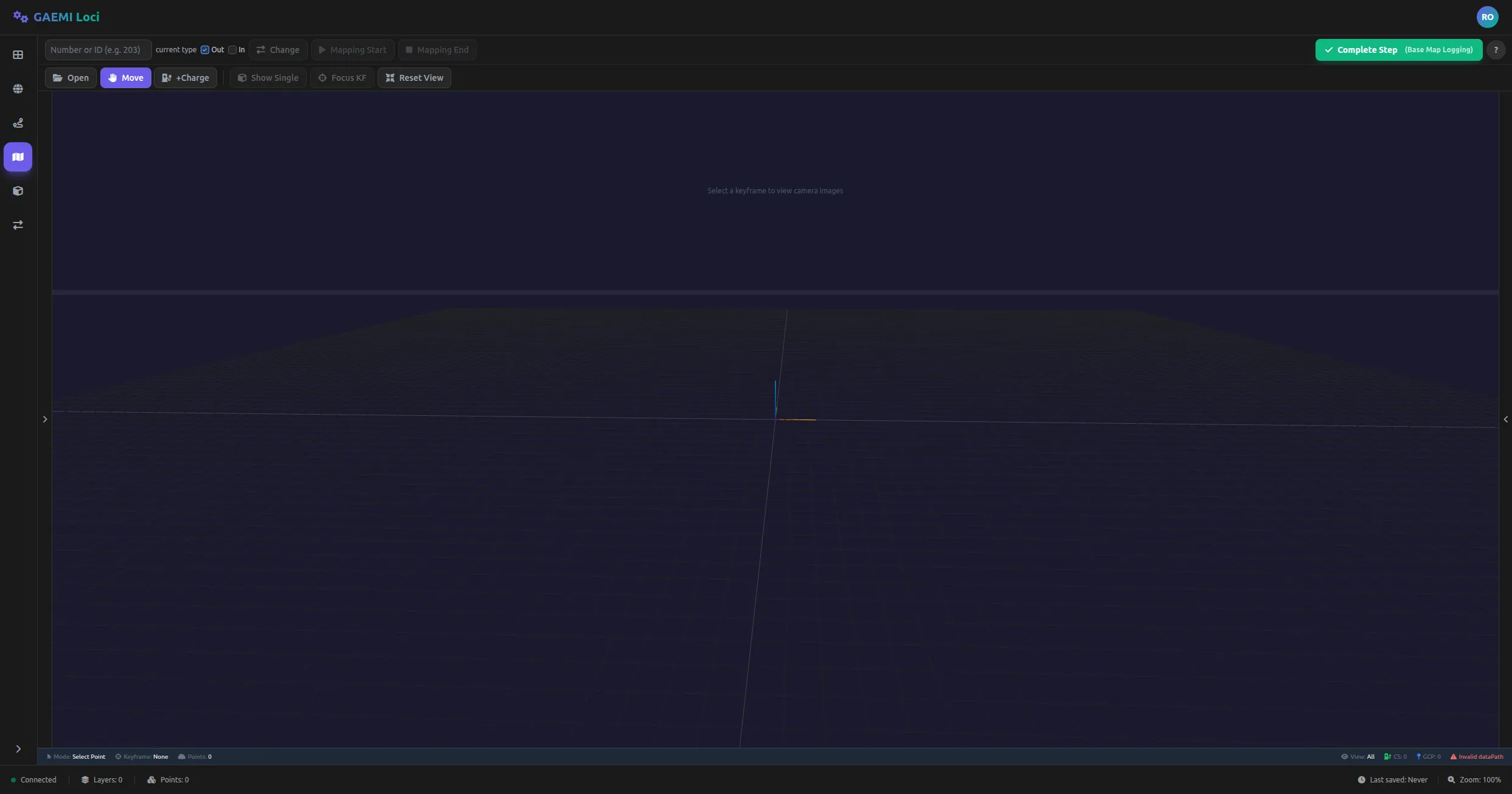
After on-site installation, connecting to the Base Map Editor displays the screen shown above. Mapping-related buttons are located in the first row of the top toolbar.
2. Enter the robot ID

Enter the robot number in the Robot ID field. Once the ID is entered, the mapping-related buttons such as Mapping Start and Mapping End become active.
3. Click Mapping Start

Clicking the Mapping Start button lets you choose the mapping type:
- Outdoor: outdoor environment mapping
- Indoor: indoor environment mapping
Once you choose the type that matches the environment, the robot switches to “Site Setup” mode through the FMS API and mapping begins.
4. Warning message

A warning message may appear during the robot’s mode transition when mapping starts. This is normal behavior, so you can proceed without any special action.
5. Verify that mapping is running correctly

When mapping starts successfully, the screen displays the “Recording…” status.
6. Mapping in progress
While mapping runs, you can watch the point cloud data being generated in real time. Drive the robot freely across the full area you want to map.
7. Click Mapping End

After driving through every area to be mapped, click the Mapping End button to finish mapping.
8. Mapping End result

When mapping ends, data upload starts automatically. Once the upload is complete, the robot returns to Waiting mode.
Elevator environment mapping
When mapping a multi-floor building, use the elevator to move between floors. Once a Robot ID is entered, the elevator-related buttons appear on the toolbar.
1. Elevator control panel
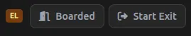
The elevator control panel has two primary buttons:
| Button | Purpose | When to use |
|---|---|---|
| Boarded | Notifies that boarding is complete | Click after the robot has fully boarded the elevator |
| Start Exit | Notifies that exit is starting | Click when exit begins after reaching the destination floor |
2. Keypad after Boarded
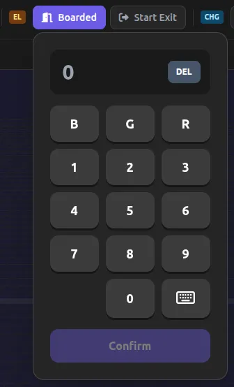
When you click the Boarded button, a keypad appears so you can enter the floor you boarded. The UI mimics a physical keypad and is designed to be intuitive.
3. Enter the floor
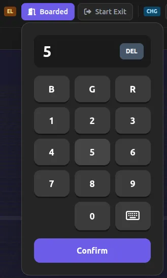
Use the keypad to enter the floor you are currently on:
| Input method | Description | Example |
|---|---|---|
| Above-ground floor | Digits only | 3 (3rd floor) |
| Below-ground floor | B + digits | B3 (3rd basement floor) |
| Special floor | G (Ground) or R (Rooftop) | G, R |
| Keyboard input | Use the KB button to switch to virtual keyboard mode | Free-form text input |
- DEL: deletes the entered characters one by one.
- Complete: confirms the input.
Entering special floors
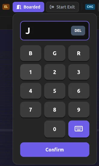
When you need to use special floor notations beyond numeric floors:
- G: enters the Ground floor
- R: enters the Rooftop floor
- KB: switches to virtual keyboard mode for free-form text input (for example,
Mfor Mezzanine,PHfor Penthouse)
You can enter up to 4 characters, and the keypad closes automatically when you click outside it.
4. Enter the exit floor
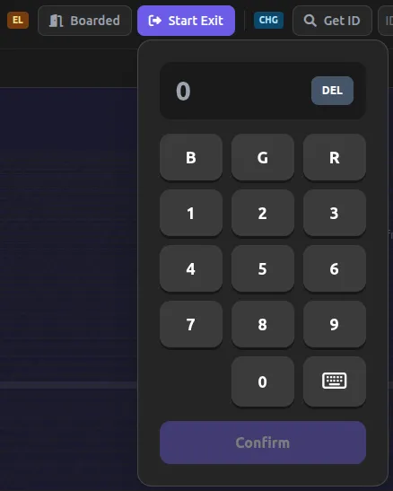
Clicking the Start Exit button displays the same keypad. Use the same floor input method as above to enter the exit floor, then press Complete to confirm.
Mapping status indicators
Several visual indicators let you check the current state while mapping is in progress:
| State | Indicator | Description |
|---|---|---|
| Idle | Green check icon | Idle state before mapping starts |
| Requesting | Blue spinner | Sending a mode-transition request to FMS |
| Polling | Yellow spinner + Manual Check button | Waiting for the mode transition (automatic polling every 5 seconds) |
| Recording | Red ping animation | Mapping data is being recorded |
| Error | Red triangle + Retry button | An error occurred; a retry is required |