Path Editing Features
The Path Editor is a tool for editing the topology-based path the robot will drive. It manages path data together with a PostgreSQL/PostGIS database.
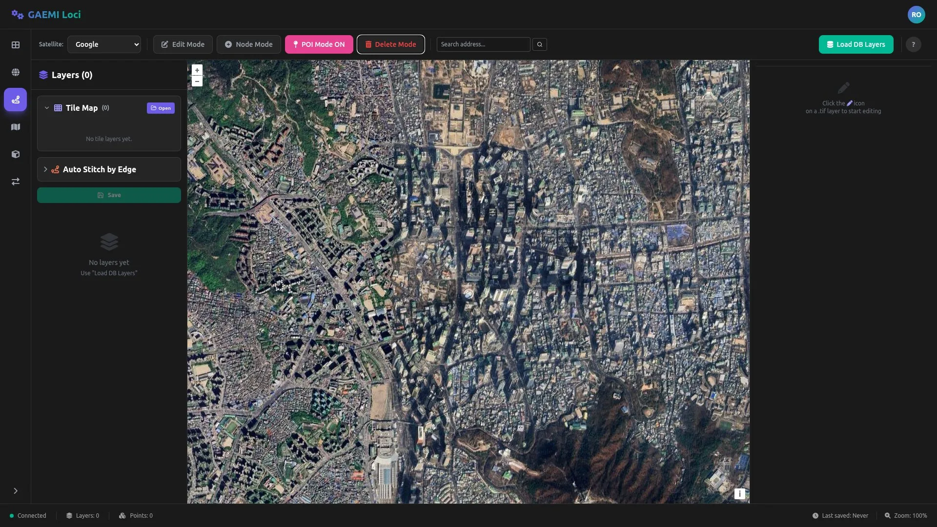
Screen Layout
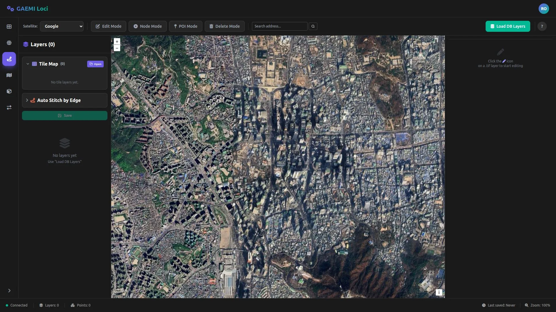
- Left panel: Layer management, property editing
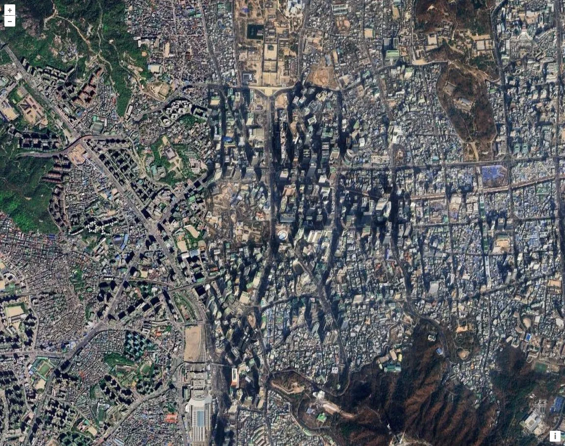
- Center area: Path overlaid on a satellite map (OpenLayers)
- Right panel: Detailed properties of the selected feature
Load DB Layers Button
A green button (with a database icon) that loads the DB layers.
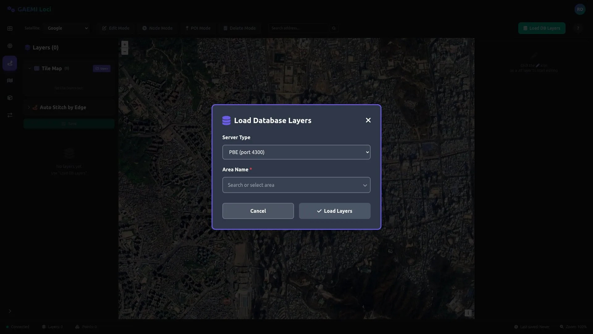
- Clicking it fetches layer data from the configured DB connection
- Displays an error message if no data exists or the connection fails
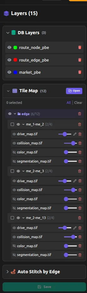
DB Layers
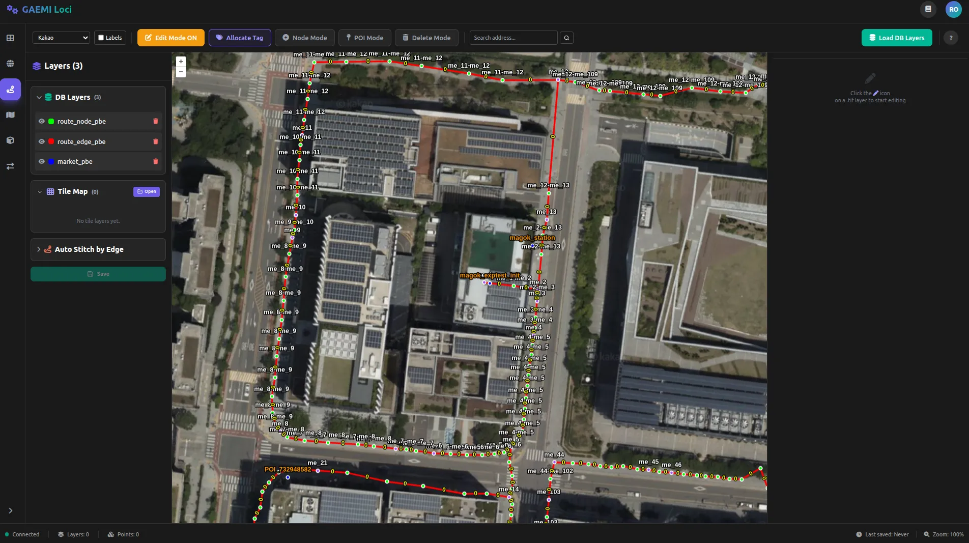
Data layers loaded from PostgreSQL:
- route_node: Path nodes
- route_edge: Path edges
- market: POIs / markers
Map Layers
Use Open in the Tile Map section to load the desired map into the map list.
Editing Modes and Keyboard Shortcuts

Switch between the following modes using the top toolbar. You can also activate each mode with a keyboard shortcut. Only one mode can be active at a time.
| Mode | Shortcut | Color | Function |
|---|---|---|---|
| Edit Mode | Q | Orange | Select and edit existing nodes/edges |
| Node Mode | W | Cyan | Add new nodes and connect edges |
| POI Mode | E | Pink | Add Points of Interest (POI) |
| Delete Mode | R | Red | Delete nodes/edges/POIs |
| Cancel/Deselect | Escape | — | Cancel the current selection |
Button States and Interaction
Each mode button has different colors for the inactive (default) and active states.
| State | Appearance |
|---|---|
| Inactive | Dark background, gray text (border-white/10 bg-white/5 text-gray-400) |
| Active | Mode-color background + white text + ” ON” suffix on the label |
| Hover | Slightly brighter background (hover:bg-[#252525] hover:text-white) |
For example, when POI Mode is active, the button shows “POI Mode ON” and is highlighted in pink.
Edit Mode (Q)
Select existing nodes and edges to modify them.
- Move node: Drag a node to change its position
- Select edge: Click an edge to edit its properties
- Multi-select: Ctrl + click to select multiple features
- When Edit Mode is active, the Allocate Tag button is additionally shown in the toolbar
Allocate Tag Button
A button that appears only in Edit Mode; it automatically assigns tags to the selected nodes/edges.
| State | Appearance |
|---|---|
| Default | Orange background + tag icon |
| Allocating | Spinner + “Allocating…” text |
| Completed | Returns to the default state |
Node Mode (W)
Add new nodes.
- Click the desired location on the map to create a node
- Consecutive clicks automatically connect the nodes with edges
POI Mode (E)
Add Points of Interest.
- Click on the map to set the POI location
- Select the POI type (charging station, waiting point, pick-up/drop-off point, etc.)
Delete Mode (R)
Delete the selected feature.
- Clicking a node or edge deletes it
- Deleting a node also deletes any edges connected to it
Property Editing
Edit the properties of the selected edge in the right panel:
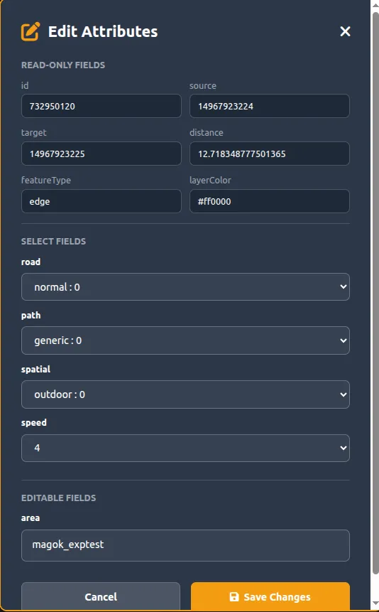
| Property | Description | Values |
|---|---|---|
| Road Type | Type of road | Sidewalk / Roadway / Crosswalk |
| Path Type | Type of path | Bidirectional / One-way |
| Spatial Type | Spatial type | Outdoor / Indoor / Underground |
| Speed | Speed limit | 0.5 – 2.0 m/s |
Satellite Map Background
Switch the background using the Satellite selector on the left side of the toolbar:
| Option | Description |
|---|---|
| Google satellite imagery | |
| Kakao | Domestic high-resolution satellite (default) |
| OpenStreetMap | OpenStreetMap topographic map |
Typical Workflow
1. [Load DB Layers] → Load existing path data from the DB2. Activate Node Mode (W) → Click on the map in order to add nodes3. Escape → Exit Node Mode4. Activate Edit Mode (Q) → Click/drag nodes to adjust their positions5. Click an edge → Set Road Type, Speed, etc. in the right panel6. (Optional) Allocate Tag → Automatically assign tags7. Data is automatically saved to the DB as soon as it is editedCoordinate System
The Path Editor supports the URDF coordinate system. Conversion between the robot’s local coordinates and GPS coordinates happens automatically.
Data Storage
Edited path data is saved to the DB immediately. Changes are reflected in real time without a separate save button.